|
|
|
- The Truth of Stress Curves - In the world of designing bamboo fly rod, Everett Garrison invented his method to calculate a rod taper from the expected stress curve in old days. This method has been considered as a scientific method of designing a bamboo rod for a long time and it is still vital even now. To brief the Mr. Garrison's method, assume that there is a rod which taper (dimensions) is known. As the rod is made from bamboo, the rod sections (each 5 inches length sections, for example) have weight. And the rod parts which are attached on the rod, e.g. ferrule (connection parts), guides, varnish, fly line along with the rod, all have their weight respectively. These respective weight will produce force of inertia when the entire rod is moved (cast) by the physical phenomenon of inertia. The force of inertia will generate a torque which we call as Moment. Each part of the rod will generate Moment, then he accumulats all the Moments which are generated by all the rod parts for each specific point of the rod (for instance, each 5 inches interval on the rod). When Moment value is calculated, the stress value can be calculated on the specific point of bamboo rod. The plot of this stress value on each rod point is a graph, which is called as Stress Curve. By looking at the stress curve, he could know what kind of rod it is. In the beginning, it is hard to understand what the stress curve means. But after repeating to make rods based on the stress curves, one can gradually feel to understand the relationships between the actual feeling of the rod and the stress curve patterns. Once we could feel to understand the relationship between the rod and its stress curve, we would like to draw a probable stress curve and want to reverse calculate its taper (dimensions) from the stress values on the rod. Mr. Garrison invented this method by using slide rule. In more older days than Mr. Garrison's, the method of rod design was "Try and Error". In this method, he makes a basic rod. Then evaluate the rod and adjust needed dimension by flipping and casting. When he feels like that he would like to bend this part of the rod a little more, he planes out that part a little more and again evaluates the rod. Even if we use any kind of design tools, this factor may remain in rod making. Well, let me introduce the design method which I invented. Though I long used Mr. Garrison's method, I couldn't have a confidence if I surely defines the desired rod by means of his stress curve. I could feel that the stress curve may be all right but I could not be for sure if the rod is really what I desires. Then I started to doubt if this is the correct way. The stress curve might not be a should-be target to design a rod taper. It is because Mr. Garrison's calculation is for structural engineering which tries to calculate the internal force of stress within a non flexure materials. As the result, when a rod is fully deflected, the stress curve around tip front section goes high even though the tip front section is stretched out actually. Thus the stress curve which I draw when I design a rod, is also not a real one. Mr. Garrison's Stress Curve The two graphs below are made through Mr. Garrison's mathematics. One is the Stress Curve and the other is a rod deflection which is calculated from the Stress Curve. The assumptions are: Payne 200 8 feet 3 pieces #4 line, line length to fish is 75 feet, rod movement is translated in the speed of 4G, the speed which forces the rod 4 times of gravity acceleration. The word PH1-PH4 on the graph legend means that the rod movement is divided into 4 phases and the calculation is made for each phase. Phase 4 is the last phase of rod movement. First look at the stress curve at left around rod point 0 to point 30. The stress values are around 25,000 psi (pound per square inch). It might over the breaking point of bamboo? This is caused by the structural engineering type calculation which assumes that the rod should not bend. Though it is not meaningful, I drew a rod deflection graph from the stress values. Right side graph is the one. Though the rod moves in horizontal direction, its tip top faces downward at phase 4. In actual world, its tip top must face to the direction where the fly line is pulling, that is toward right horizontally.
Rod deflection is also difficult to draw. We cannot see how the rod deflects while casting the rod. But we can look at the deflection when our friend is casting. Anyway, it is sure that the rod deflection is more practical bjective than stress curve. Then, I developed an Excel tool to draw an objective rod deflection. This tool can draw any kind of rod deflection in a good shape. The resulted data is passed to DynaRod and DynaRod produces the rod dimensions through making various complex calculations. The most difficult thing in developing DynaRod was its dynamic calculation. Where time duration must be considered. The calculation is made by chasing the shape of the rod from time to time. This costs computer time a little but the result shows the realistic shape of the rod and stress curve. When a rod is fully bent, tip top will be stretched and the stress curve reflect this either. Stress Curve of DynaRod The next graphs are the output of DynaRod. Left is the one for rod deflection and right is corresponding stress curve. Assumptions are exactly same to the one which is shown above. Payne 200 8 feet 3 pieces #4 line, line length to fish is 75 feet, rod movement is translated in the speed of 4G, the speed which forces the rod 4 times of gravity acceleration. On the rod deflection graph at left, horizontal fly line is pulling the tip top toward horizontal right direction. On the stress curves, the stress values of tip front becomes lower to show that the part is stretching from phase to phase.
In Mr. Garrison's mathematics, what is the meaning of "multiply 4 to the weight of all the rod parts"? The meaning of "4 times of weight" can be described in such a manner as if we were in the space. Weight=mass x gravity acceleration at 1m above the surface of the each. On the other hand, when we move a rod in a certain acceleration, the force which the rod receives is calculated by the formula, Force = mass x acceleration. In DynaRod, as all the calculation are done from the space oriented view point, all the rod parts weight are converted into the mass value. Then the meaning of "4 times of weight" becomes; the entire rod, that is, fly line, top guide, snake guides, stripping guide, bamboo sections, ferrules are moved together in 4 times of gravity acceleration. In other words, it assumes the rod is moving as shown in the graph below from right to left. The vertical rod is moved horizontally. This casting style is called as "Translated Rod" casting. You hold the rod vertically and push your hand forward. The skillful tournament caster must use this style. Mr. Garrison and his math calculates the rod taper in this assumption. 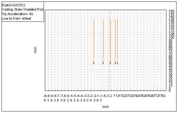 Then the rod deflects like below. (simulated by DynaRod). This deflection is the shape of the first resonated vibration. This resonation can load fly line weight to the extents of maximum. Then the maximum force can be stored on the rod. In general, the caster can feel that the rod is fully loaded. 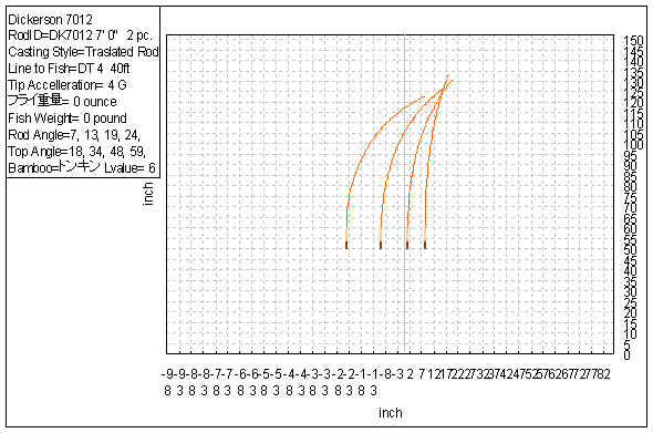 On the other hand, we may not do this kind of casting in our actual fishing, do you? Perhaps, we may throw our fly by the following casting. As the rod is turned around the grip as a center, it is called as "Rotated Rod" casting. 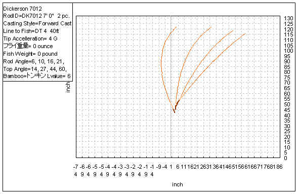 This deflection is the shape of the second resonated vibration. You can make this deflection by flipping your rod up and down, or right and left. (referring to the left most curve on the above graph). The load on the rod becomes less in comparison to the "Transfered Rod" case. It is easy to feel the load on the rod by actually flipping the rod in both ways respectively. Or think about like this, in the "Rotated Rod" casting, the tip top is travelling more distance and the grip part moves less distance, in the same time duration. It is obvious which part of the rod receives more acceleration. It is sure that the tip front receives more force of inertia. We can say that this casting style is the one which throw the entire line load by the front half of the rod. Well, let's see the stress curves of the above cases respectively. Mr. Garrison's case, the case of "Translated Rod" shows the stress curve of the next graph. We can know that almost equal stress value is distributed over the rod. (blue line). 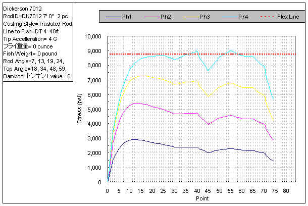 On the other hand, "Rotated Rod" casting shows the following stress curve. The stress of the tip front goes high and that of grip front stays low. The interesting thing is that both are the stress curve of the same rod. 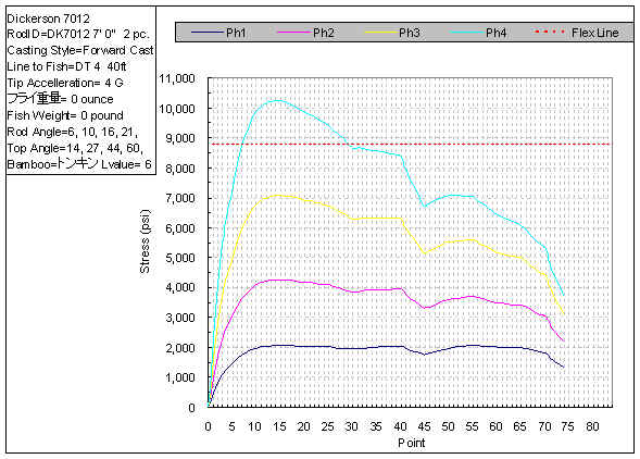 Now let's come back to the main issue of this article. Do those who design rod taper by Mr. Garrison's method, know that you are assuming the "Translated Rod" casting? If not, when you draw such a stress curve as descibed in the "Master Guide", left up, right down, it is very probable to have a rod taper which butt section is very hard. Though I guess the rod can be used.... When you are ordered to make a good tip action rod which is used in actual fishing field, do you see the resulted rod taper by multiplying 4 over the entire rod parts, I mean by "Translated Rod" assumption? I guess that the skilled rod designer who knows well about the above differences, can design a good rod taper by trial and error. But it is also probable that the good tip action rod might have a little harder butt section than the "to be" taper. DynaRod can prevent the misled design caused by the misunderstanding. Designing a rod deflection as the target, and applying the assumption of "casting style" to it, DynaRod made it possible to design the rod practically. Of-course, after understanding the above effects well, the design method by stress curve can be usable as it is also packaged within. Interesting? I think there must exist more useful rod taper than the one which we produce now. Max Satoh June 11, 2007 |
||||||||
| © 2019 Far North Rodsmiths |